
Thanks Sweetheart!
To begin, when I originally wanted to start my pump project, the March 809 pumps were selling for about $110. Fast forward to about a year later--the lowest price has been steady at around $140. An online source called Chugger Pumps has the best price by far ($125). However, their +$12 shipping makes them only about $2 less than the other guys. Needless to say, I was bummed at the nearly $30 increase in cost I was looking at paying. I was keeping my eye on ebay because everyone I know that has a pump and a great majority of HBT'ers have purchased their March pumps from USA Pumps on ebay. I caught a break when I saw a listing for $121.99 with free shipping, that was $18 less than most online prices, and it was $16 less than Chugger Pumps! There were only two available, so I got permission from the finance department, and grabbed one.
Before I get into the actual build I want to make it clear, this isn't just a pump-in-a-tool-box build, this is the beginning of my no-sparge phase in my brewing process, hence the many additional fittings and such that you will see in my build parts list. Having said that, on to the show.
Here is my build parts list, it will be updated as necessary:
(This is an interactive table, almost all parts are linked to the source, so click on any item you are interested in and the link will open in a new window.)
Beyond the pump itself, the backbone of this build is the enclosure the pump is mounted in. I chose a tool box that is over sized. If you plan on tackling a DIY portable pump-box for yourself, my suggestion would be to err on the large side, you can never have too much storage for all of your brew day gear.

note: Of course, there are a couple of fittings that aren't in this photo because I had to make a supplementary order. The missing fittings are mainly for my MLT and the kettle lid for recirculation during no-sparge brewing. They are on the build list, but will come much later in this post, or in the following posts concerning the no-sparge brewing method.
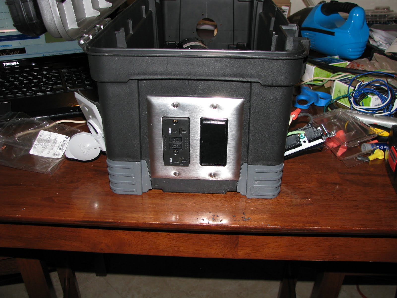
There is one item that I think sets my box apart from the many I have seen, and that is the male receptacle:

This little beauty allows me to use any standard extension cord for a power source, sweet!

The next task to take care of was to cut the openings for the gang-boxes so they could be installed, and to cut the hole where the pump was to be mounted.

I have found that using a Dremel to cut plastic makes a mess, and in my opinion, isn't worth the hassle. My preferred method is to use a utility knife. The cuts are cleaner, and you have more control over the size of the hole being cut. It takes a little more elbow grease, but the end result is well worth the additional effort.

All I had was a 2 3/4" hole saw on hand which was much too large, a fellow brewer was kind enough to lend me his 2 1/8" hole saw which was perfect for cutting the hole for the pump.

The old-work gang-boxes are a snug fit.


Next comes the wiring, I will provide a few pictures of some of the wiring, but all of the wires look like a jumbled mess inside the gang-boxes. I think this diagram does more justice than the photos and is easier to understand.

Wiring the main power/male receptacle, (Green=Ground, White=Common, Black=Lead)

Here is everything you need to know about GFCI's, and their installation.
This is an image of the completed wiring in the box. Like I said it looks messy in the gang-box. However, I will provide a list of how the wiring attaches in sequence, and you can refer back to the wiring diagram for verification.
(Male-Receptacle Common connects to the Silver screw on the Load-side of the GFCI, and the Lead wire connects to the bottom Brass screw of the Main-Power switch. A Lead wire is then jumped from the Brass screw of the Load-side of the GFCI to the top Brass screw of the Main-Power switch, a Ground wire is attached to the Main-Power switch Ground screw [this completes wiring of he Main-Power switch]. Jump a Lead wire from the Brass screw on Line-side of the GFCI to the bottom Brass screw of the Pump-Power switch, attach the Lead wire from the Pump the top Brass screw of the Pump-Power switch, and connect a Ground wire to the ground screw of the Pump-Power switch, then connect the Common wire from the Pump to the Silver screw on the Line-side of the GFCI. Wire nut all Ground wires to the Male-Receptacle ground wire [this completes the wiring for the box.] note: cap all loose wires with wire nuts.)

GFCI and Main-Power switch installed:
A semi-finished photo with the Pump-Power switch installed.

Corner shot with the Male Receptacle, GFCI, and Main Power switch.

...and the opposite side featuring the GFCI, Main Power switch, and the Pump Power switch.

...Pump Head installed...

Finally all box installations, and wiring complete. (look at that clean wiring!)


Ball valve, reducing coupler, and male camlocks fitted to the Pump Head.


I believe that does it for the Pump-In-A-Tool-Box-Build.
I have yet to brew with this beauty that will be this weekend (15-May-2011, if a catastrophe doesn't occur). Hopefully I will have some photos of brew day with he pump in action. This brew day will more than likely be a standard brew day rather than a no-sparge brwe day. I just got this bad boy together. I need to figure out exactly how it will be integrated into my brew day before I attempt to start an entirely different way of brewing.
It is my understanding that no-sparge brewing can cut a decent amount of time off of brew day, but there are some drawbacks, such as lower brew house efficiencies due to the lack of sparging/rinsing the grain of sugars.
I plan on brewing a 10 gallon batch of a BriticA, which will be a 50/50 - US 2-row/English Marris Otter base malt, with a bit of Munich and Crystal 40L, basically an APA/BPA, but I will be using American hops, Chinook and Amarillo. However, I will split the batch, and inoculate each 5 gallons with dfferent yeasts, WLP 001 California Ale, and WLP 023 Burton Ale. So I will have a more American APA with some Marris Otter, and an English ale Ale with American Hops...It will be interesting.
Thanks for following, I hope this post inspires you if you are interested in a portable pump setup.
Please comment!

What's plugs into the two external outlets?
ReplyDeleteAnything I might need to power. I use the additional outlets to power a submersible pump that I use to recirculate ice water through my immersion chiller when chilling the wort to pitching temps.
ReplyDeleteThanks a lot for posting the build. it will come in handy when I start AG brewing :)
ReplyDeleteThanks for posting this write-up of the toolbox pump project! It was a huge help. I just completed my build with only one small hiccup: Your wiring diagram shows the "Line" and "Load" labels reversed. I wired it as per the diagram in this write-up and got no power through the GFCI. A voltage meter told me my extension cord was good and the hot was live to the main power switch and then on to the GFCI but beyond that there was no juice. I consulted the instructions that came with the GFCI and it instructed me to wire the power source to the "Line" side and then wire any additional outlets to be protected in the circuit to the "Load" side. In this case we are protecting the pump instead of an additional outlet. Well I rewired it, swapping the wiring on the GFCI and everything works great. Just wanted to give you a heads up on that little issue.
ReplyDeleteThanks again,
Patrick
Great write up, I am thinking about using this method for my control box. However I have a plug in pump and I dont want to strip the wires, So I would have mine just plug into a switched outlet, and I may use a waterproof cover for that as a result.
ReplyDeleteI also want to add a PID for moniotring temps at some point too. Have you thought about adding one of those?
Nice work!
-Jesse
Thank You and that i have a dandy supply: Whole House Renovation Cost Calculator Canada renovate my house
ReplyDeleteThis sounds like an exciting project!
ReplyDelete